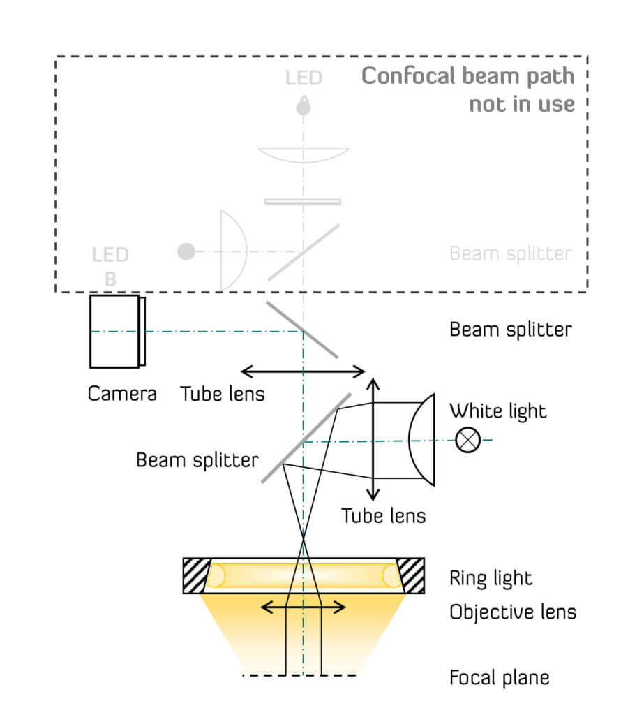
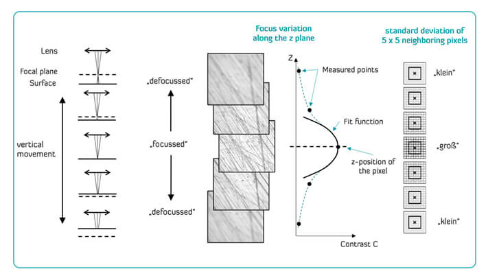
Focus variation takes advantage of the limited depth of focus of the lenses and the contrast of the surface in the sharp area of the image. The height information required for a 3D image is obtained by varying the focus position. The optical beam path uses a white light source (LED) and two beam splitters which image the light from the white LED into the focal plane and back onto the camera. In addition, a ring light illuminates flank angles larger than 80°. For the calculation of the measuring data, the contrast curve from the captured images is used in immediate proximity to each other (e.g., 5×5 adjacent pixels). This produces a contrast curve along the focus curve for each pixel and thus the corresponding height information for the measuring point through a Gaussian fit.
Confocal microscopy and focus variation
Confocal microscopy and focus variation in one measurement system
The range of application of Confovis measurement systems with patented optical measurement method (Structured Illumination Microscopy, “SIM”) is extended by the use of focus variation.
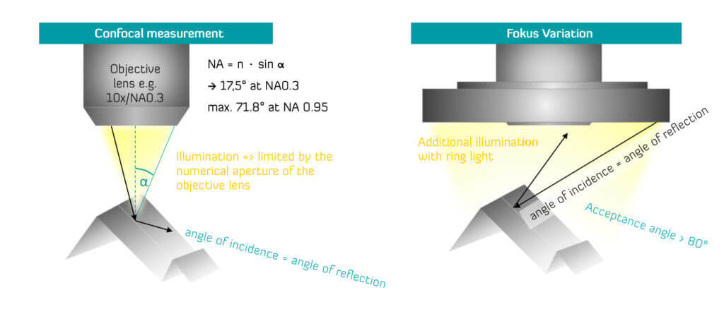
As opposed to confocal microscopy, only the surface contrast is used to generate the measurement data. Thus, flank angles above 80° can also be captured by means of ring light illumination – independent of the numerical aperture (NA) of the lenses and therefore the magnification.
For the measurement of form and other geometric features (e.g., chipping and wear measurements of cutting tools) the focus variation complements confocal microscopy perfectly: Highly reflecting and fine surfaces, such as monocrystalline and polycrystalline diamond, silicon or silicon dioxide, are very low in contrast. As a result, they cannot be measured in sufficient detail with focus variation. In contrast, cutting edges of tools with small wedge angle can be measured reliably with focus variation.
Data fusion from confocal microscopy and focus variation
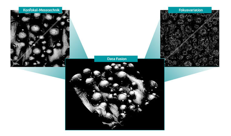
Data fusion is the combination of focus variation and confocally measured 3D surface data in a common coordinate system.
The measuring point density obtained with focus variation is smaller than that with the confocal measuring method due to the lower resolution. High-reflexion, low-contrast surfaces, in particular, mark the physical limits of focus variation. For this reason, the combination of both measurement methods with data fusion provides a solution for recording essential geometric dimensions (wedge angle, cutting edge radius) and high-resolution roughness measurements (for example: additive manufactured surfaces show the limits of each method and the advantages of using the data).
Focus variation as an additional measurement method
Example: Comprehensive tool analysis with data fusion
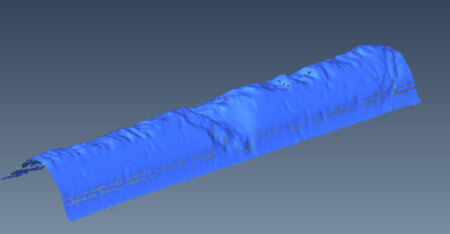
For areas where chipping and roughness are important, confocal measurement technology is used. The high lateral resolution of the confocal measurement highlight breakout and chipping of the cutting edge. This data quality is also obtained with surfaces difficult to measure, such as monocrystal diamond (MKD), polycrystal diamond (PKD) or various coatings.
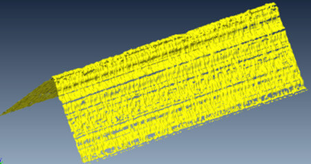
For the measurement and evaluation of steep flanks, the cutting edge is measured with focus variation and ring light (lens 10x/0.30 NA). This measurement is suitable for determining the geometry data, the cutting-edge radius can also be evaluated reliably. However, a defect in the cutting edge is hardly visible due to the lower data density.
Data fusion from confocal microscopy and focus variation
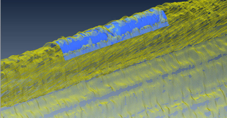
Combined measurement data of the cutting edge of a cutting tool measured with focus variation (yellow point cloud) and a confocal (blue point cloud) using data fusion.
The fusion of the point clouds makes it possible to combine the advantages of both methods.
ARE YOU LOOKING FOR A SOLUTION FOR YOUR APPLICATION?
CONTACT US!
- Fast and with nanometer
- Flexible
- High level of automation
